
Design of an active noise reduction system using phase opposition, combining theoretical, experimental, and electronic approaches. The system is developed in three stages: speaker experimentation, electrical modeling, and digital implementation on a Raspberry Pi.
Introduction
Noise is a mechanical vibration of a fluid that can be measured in decibels (dB). Prolonged exposure to excessive noise can lead to stress, loss of concentration, and eventually hearing disorders. There are two main methods to reduce noise:
- Passive reduction, which relies on acoustic absorption or isolation through specific materials
- Active reduction, which relies on generating a sound signal in phase opposition to cancel an unwanted sound wave
Active reduction is particularly useful for attenuating certain precise frequencies and complementing the limits of passive reduction. However, it requires a high-performance electronic system capable of analyzing and processing sound signals in real time.
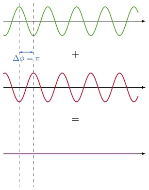
Figure 1 - Phase Opposition Simulation
1. First Experiments
a) Destructive Interference with Speakers
The first experiment consisted of generating phase opposition between two speakers to create destructive interference and reduce perceived noise.
- Two speakers were placed facing each other and powered by a signal generator with a 180° phase shift
- Noise reduction was measured at different distances, and efficiency reached up to 93% for a frequency of 440 Hz
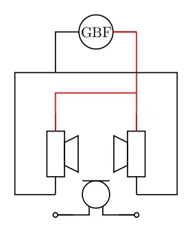
Figure 2 - First Setup Diagram
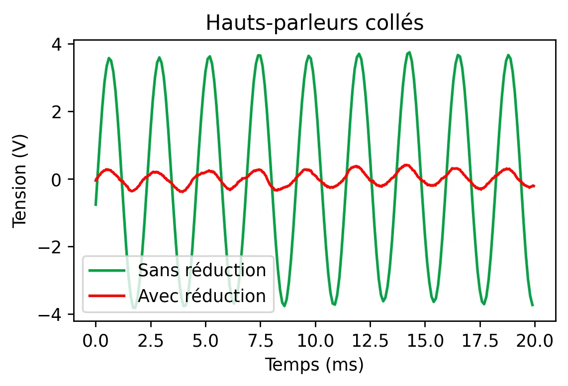
Figure 3 - Associated Results: 93% Efficiency
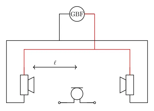
Figure 4 - Second Setup Diagram
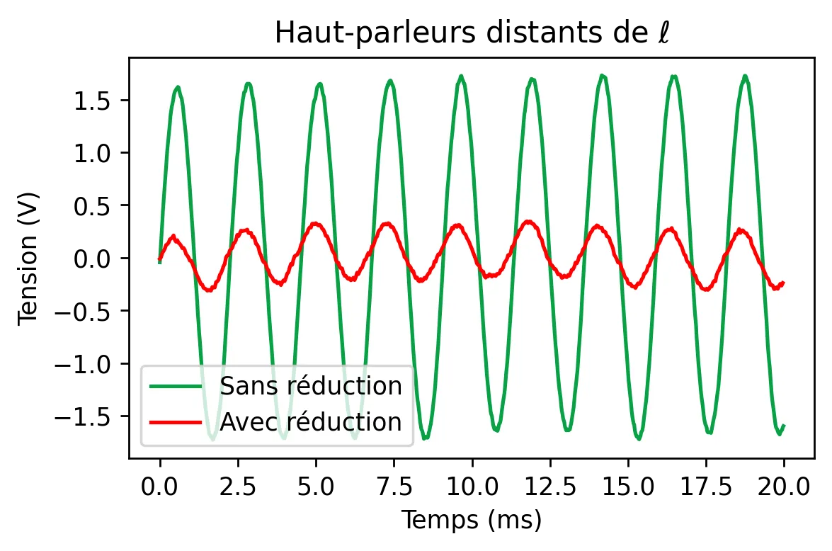
Figure 5 - Associated Results: 86% Efficiency
The experiment revealed that speaker positioning and sound wave reflections strongly influence cancellation efficiency.
The experimentation highlighted several limitations:
- Efficiency decreases significantly in the presence of sound reflections on surrounding walls
- A perfect phase opposition is difficult to maintain across the entire sound spectrum
- The measurement environment must be controlled to limit external interference
These observations motivated the implementation of a more precise electrical system allowing better control of the generated signal.
b) First Electrical Modeling
The objective was to design a circuit capable of generating a phase-shifted signal in phase opposition with ambient noise.
- A sinusoidal voltage of 1 kHz is sent to a circuit composed of resistors and capacitors to produce a phase shift via the function
- The obtained signal was then added to ambient noise via a summing amplifier, thus simulating noise cancellation by superposition of opposite waves
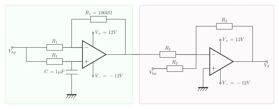
Figure 6 - Phase Shifter-Summer Circuit Diagram
A first circuit was assembled and tested:
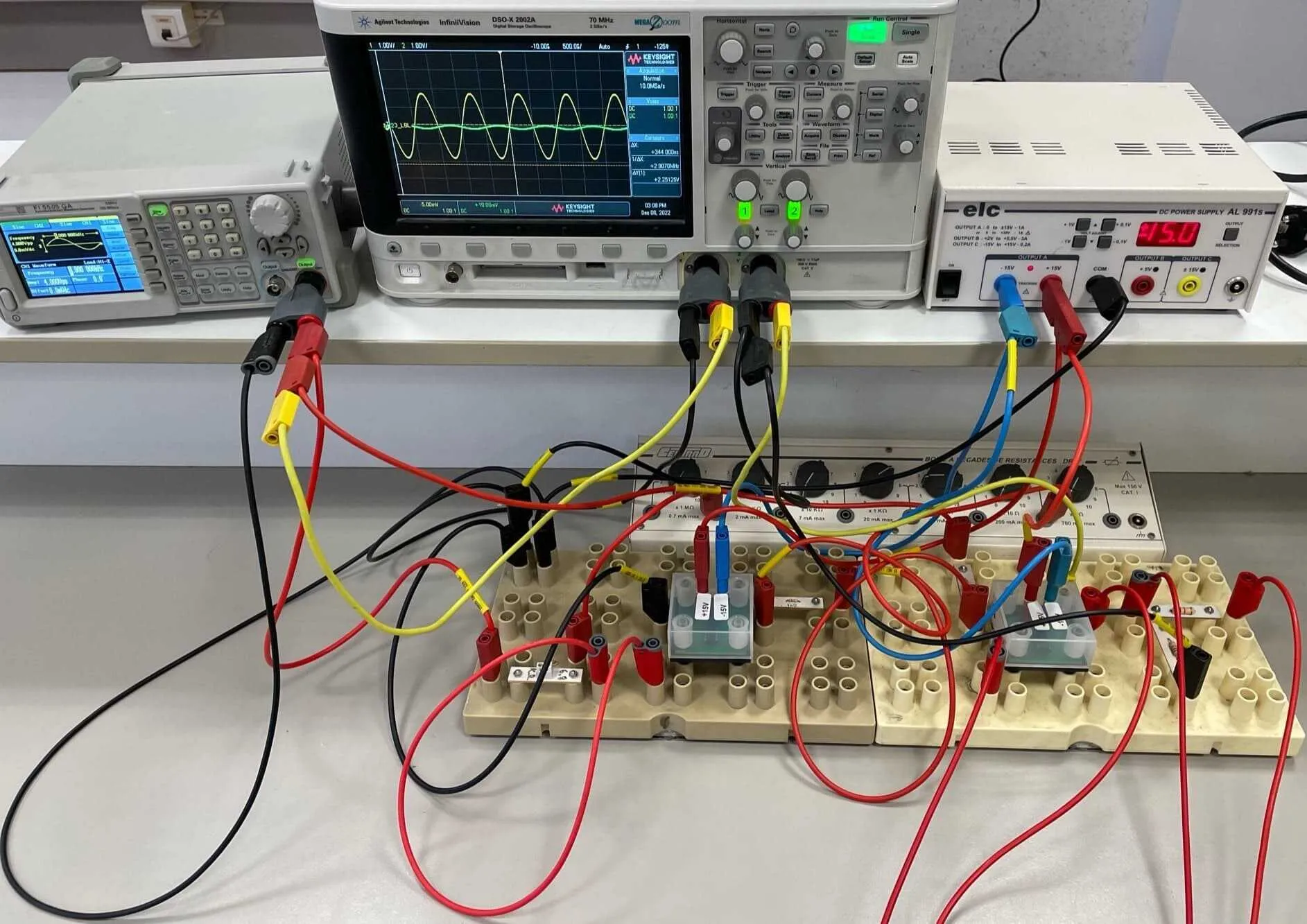
Figure 7 - Electrical System
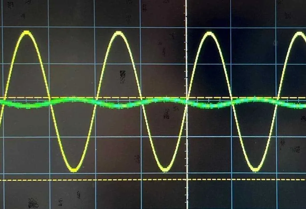
Figure 8 - Measured Associated Results
We can measure that the sound reduction reached 95%, which validates the model’s feasibility. However, electronic component values showed uncertainties of approximately ±10%, which can limit the accuracy of the obtained phase shift and also explain the value discrepancy.
2. Electrical System
This circuit aims to simulate a more classic use of active noise reduction principle as seen commercially: cancellation of ambient noise to keep only the sound we chose. For this, we process an input signal that we then sum with music.
The noise is therefore the music played that we try to remove from the signal sent by the GBF.
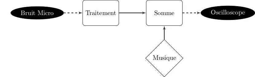
Figure 9 - General System Principle
We then assembled and tested our system:
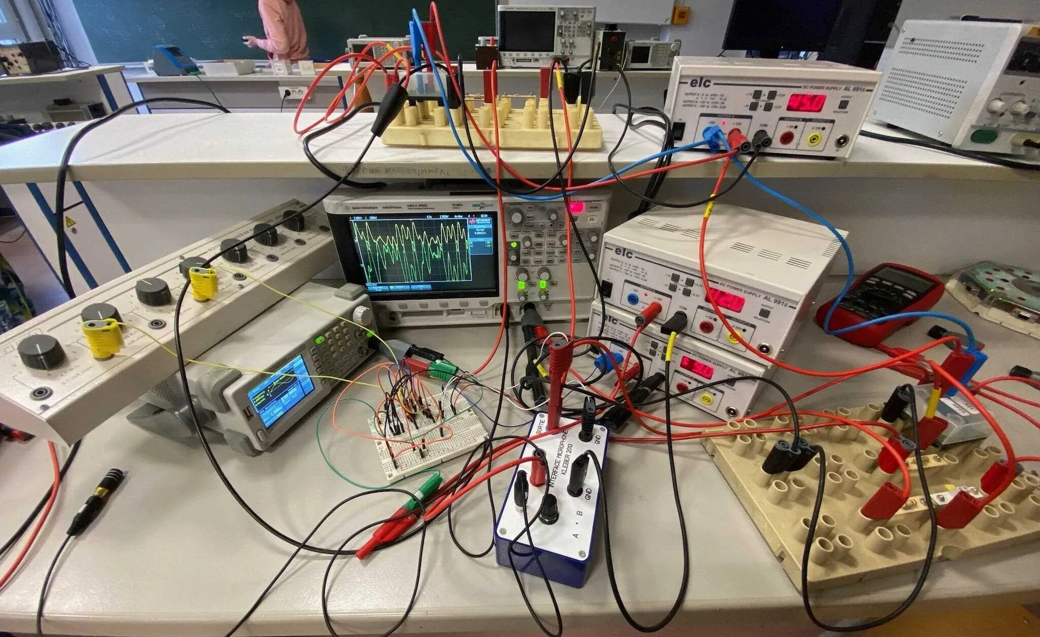
Figure 10 - Electrical System
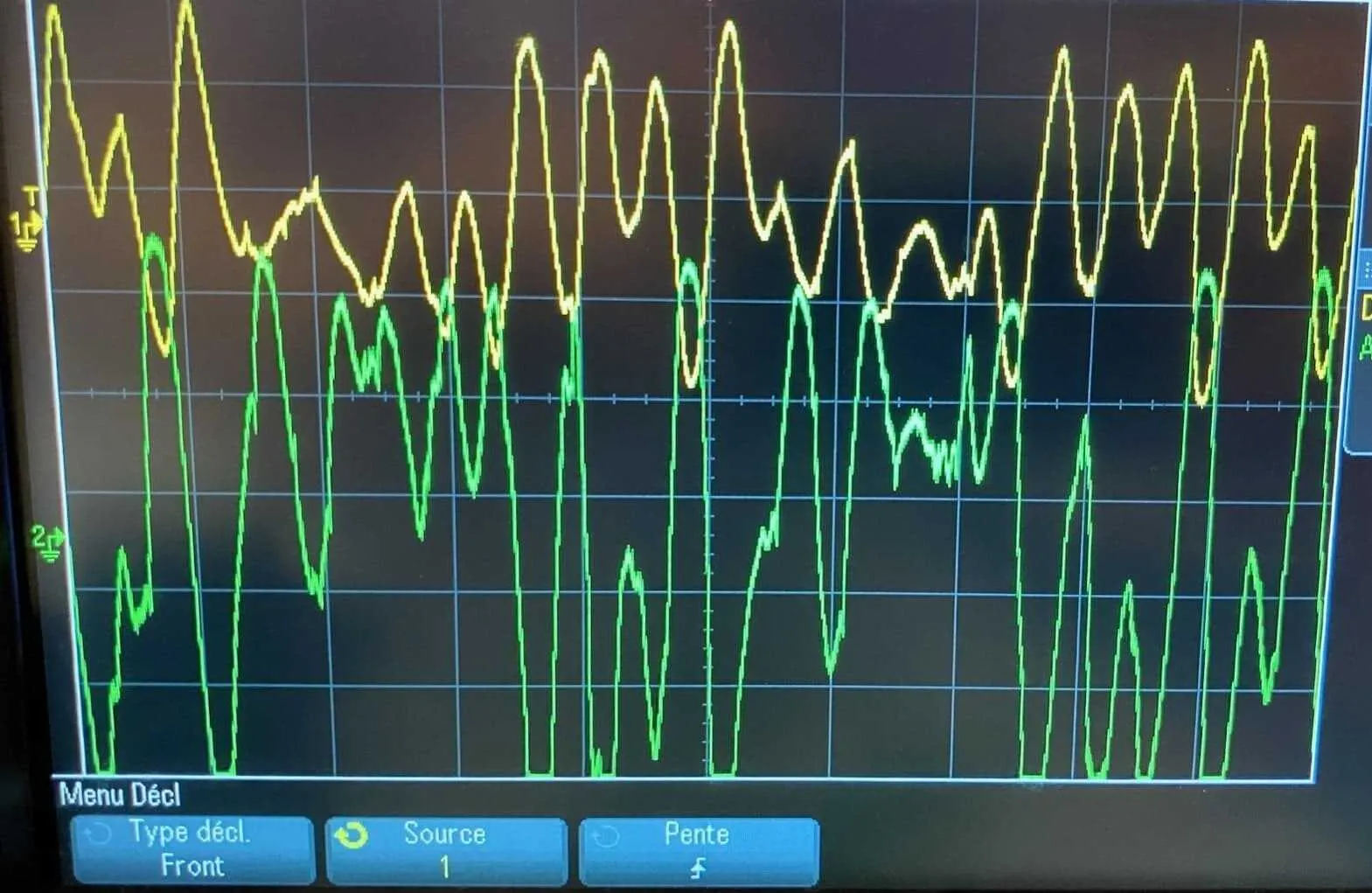
Figure 11 - Measured Associated Results
With the green curve showing the signal without reduction and the yellow one showing the signal with noise reduction, we can see that efficiency is questionable and still quite unsatisfactory for a real system. This leads us to change how we process the signal and therefore bring electronic processing to our final system.
3. Electronic System
a) Using a Sysam Board
To explore this new possibility, we developed a signal processing program in Python to record a sound, process it with our program through the Sysam board, and then send it back to another speaker. Experimentally, we started with a sinusoidal signal that we phase-shifted to clearly evaluate our solution’s efficiency.
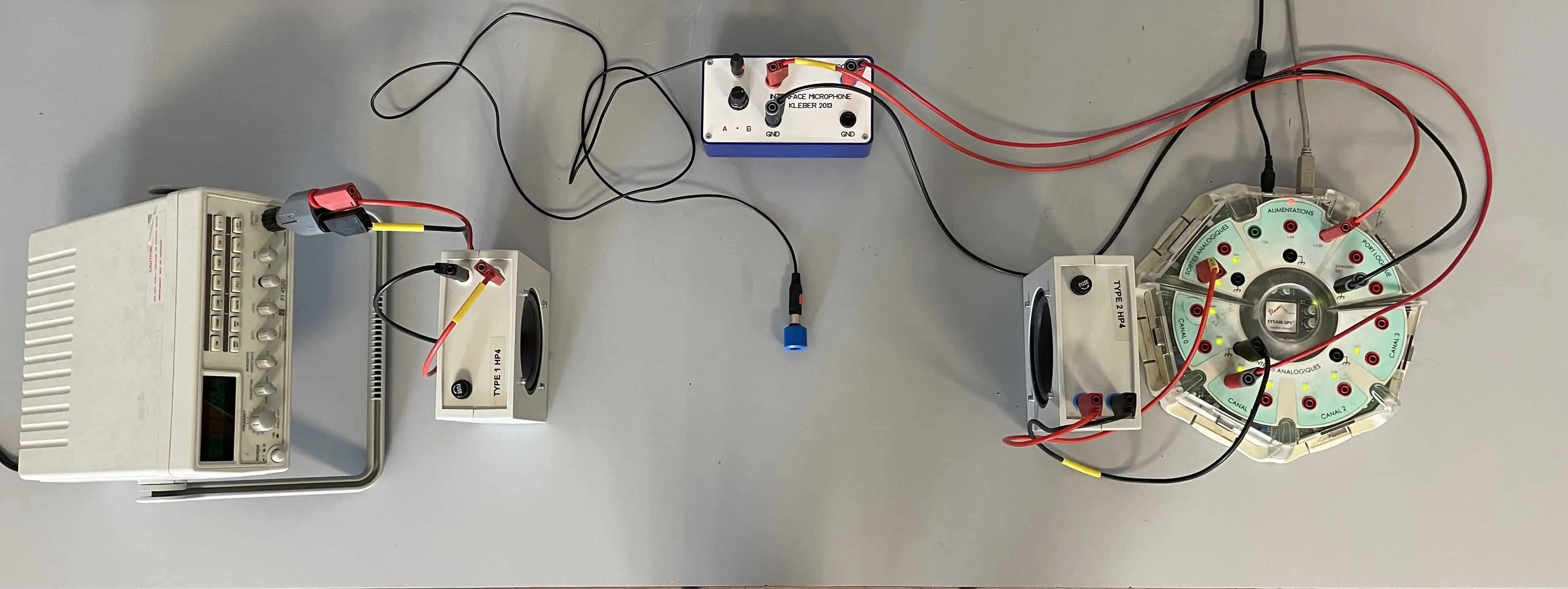
Figure 12 - First Electronic System with Sysam Board
However, the experiment showed us that for work as precise as active noise reduction, the Sysam board was far from fast enough to process the signal. The quite poor results we obtained therefore led us to consider a more advanced option including a Raspberry Pi for signal processing.
b) Digital Implementation with a Raspberry Pi
To automate sound signal analysis and correction, a digital system was developed using a Raspberry Pi and analog-to-digital (ADC) and digital-to-analog (DAC) converters. This adds additional constraints on input and output signals, as they must match the amplitudes and voltage ranges required by processing components.
The implemented protocol then includes several steps:
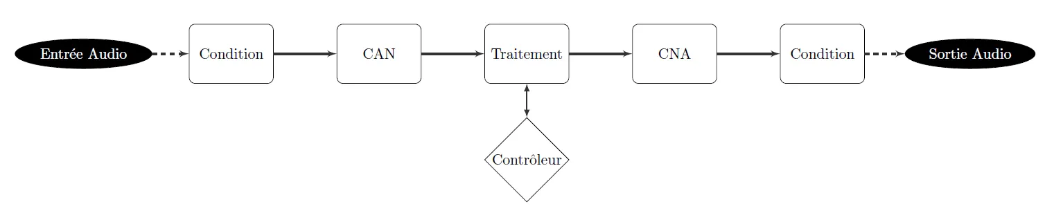
Figure 13 - Signal Processing Protocol
For input signal conditioning, we decided to use a summing amplifier to shift the voltage range above with an amplitude of .

Figure 14 - Summing Amplifier for Input Conditioning
For the output signal, we observed that the Raspberry Pi’s low sampling rate caused sharp edges at output. We therefore chose to use a low-pass filter to remedy this.
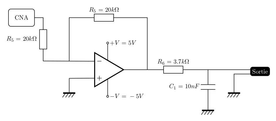
Figure 15 - Low-Pass Filter for Output Conditioning
A user interface system was also designed to dynamically adjust system parameters:
- A rotary encoder allows modifying noise reduction intensity
- LEDs indicate system operating status
- A Python script manages all peripheral processing and sound signal optimization
Finally, we were able to model the final circuit and build it:
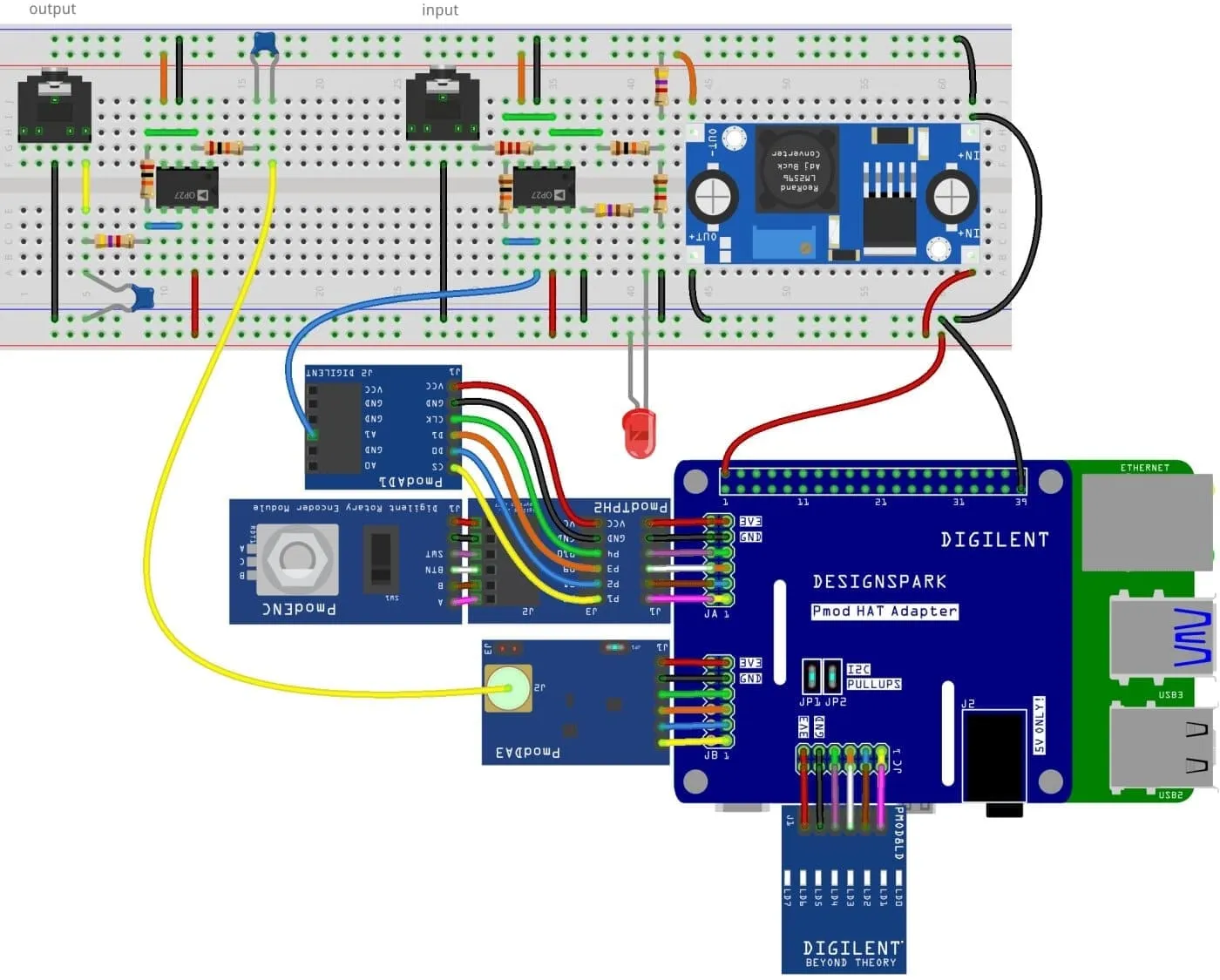
Figure 16 - Final Project Modeling
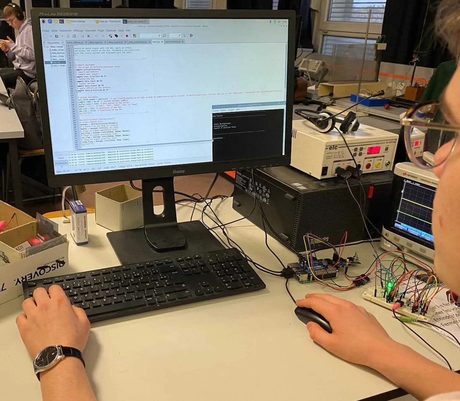
Figure 17 - System in Working Condition
However, implementation on the Raspberry Pi posed several challenges:
- Processing speed was insufficient, introducing a time delay making cancellation ineffective
- A sound distortion problem was observed at output for no apparent reason
- Some Raspberry Pi output pins were damaged during tests, making final implementation impossible
The practical implementation could therefore not be carried out despite the prior development of all the theoretical work. However, I am convinced that given the promising results from other experiments, this system could surely have succeeded. The last two systems being very complex and time-consuming, we could also have explored other avenues:
- Portable miniaturization of the intermediate system
- Finding an equivalent to the Sysam board less complex than the Raspberry Pi
This project might interest you
 2024
2024Creation of a Radio
Designing and building an FM receiver with filtering and demodulation.